How I Automated My Windows to Open/Close with The Push of A Button

When I first moved into my house, there was no AC. I found myself either leaving windows open during the night, or waking in the early hours of the day to let in the cool morning air. Similarly, as the day went on, I would need to consider the best time to close my windows so that I did not end up letting warmer air inside. Eventually, I installed AC since no matter how well I operated my windows some days were simply too hot.
To minimize my energy consumption, I was constantly thinking about when to turn on and off my AC and open/close my windows. Manually making these adjustments was a lot of work! This inspired me to create an actuator system which would open and close my windows, and use Home Assistant to automatically control both my windows and AC to minimize the cooling from my AC by using my windows as much as possible. This post will discuss how I created the actuator system and connected it to Home Assistant. Check out the sequel to this post here, where I create the logic which automates both my windows and thermostat.
Constraints and Part Selection
Replacing my windows is not an option, so the system needs to connect to the existing window crank mechanism to open and close my window. It also needs to be easily removable so that the regular crank arm can be reinstalled if ever we need to - I won’t live in my condo forever! It should also be covered in such a way that it is appealing to look at.
Let’s consider the components fo the system:
A motor: The primary consideration in this case is the torque required. The crank shaft requires a noticeable amount of torque to close the window, particularly to close the window from 90% to 100%. If we want to connect the motor directly to the crank shaft, we will likely need some significant torque. The other consideration is positional accuracy. We don’t need accurate intermediate positions of our window, only that we can accurately determine when the window is fully closed. Therefore, do not need a motor which allows for precise positional movement as we can use a sensor to determine an accurate final limit position. In this case, a simple geared 12 V DC motor should suffice. A stepper motor may be useful, however DC motors are simpler to operate and therefore will reduce the complexity of the system and hopefully increase it’s longevity. A DC motor will give us a good amount of torque without spending a significant amount of money. To change the direction all we will need to do is change the polarity. Note that geared DC can come in several options of gear ratios but the cost of more torque will be RPM. We can don’t need our windows to open very fast (and in fact it may be dangerous to do that), so in our case we can select a higher gear ratio as we are more concerned about torque than speed. The exact amount of torque will depend on individual windows as I have found them to differ significantly. (Amazon, $25)
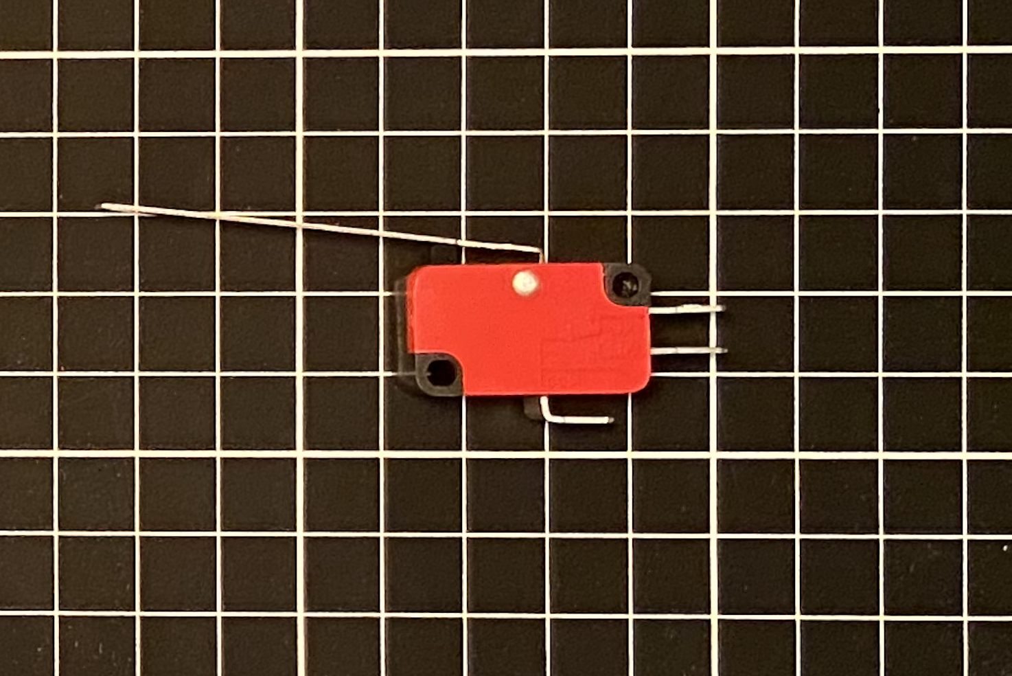
A sensor: To determine when the window is fully closed, a limit switch should work quite well. If installed in the correct position, it should trigger as the window becomes fully closed and can be used to stop our motor immediately. (Amazon ,$10 for 6)
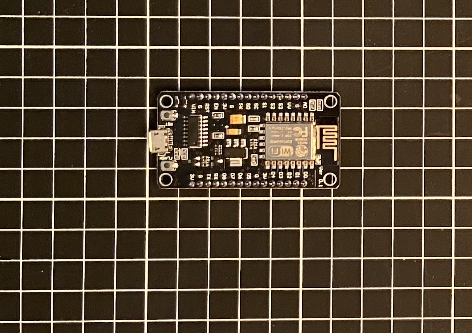
A microcontroller: The simplest way to interface a microcontroller with Home Assistant is to use something which works with ESP Home (if you don’t know about ESP Home prepare to be amazed! Read about it here). This requires a device with an ESP32 or ESP8266 chip. We don’t need many inputs or outputs, just a few GPIO pins. The Node MCU ESP8266 should work since they are relatively cheap, easy to source and work well with Home Assistant using ESP Home. Amazon sells them for less than $10 a piece and you can get them within a few days. (Amazon, $19 for 3)
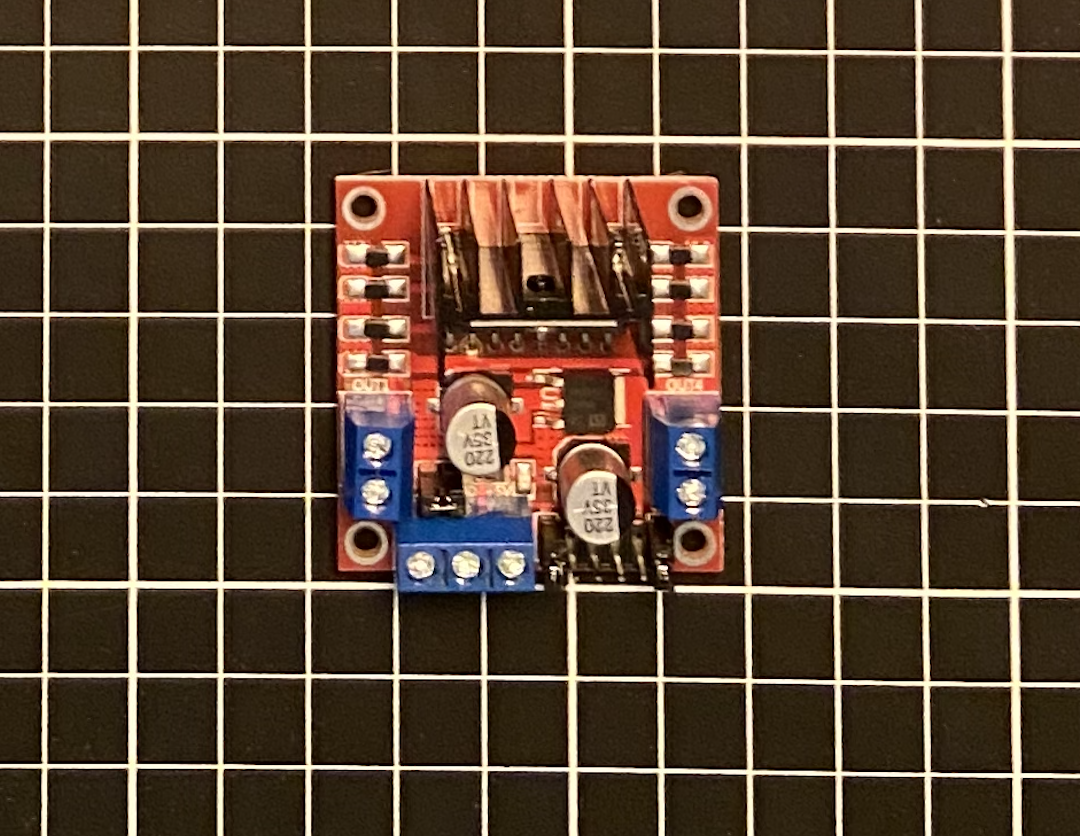
A motor controller: Our motor will need its own controller which interfaces with our micro controller. Something like the L298N works quite well and is relatively cheap. It allows for a 12 V input and can power up to two motors. It also includes a 5 V output which we can use to power our micro controller. (Amazon, $26 for 5)
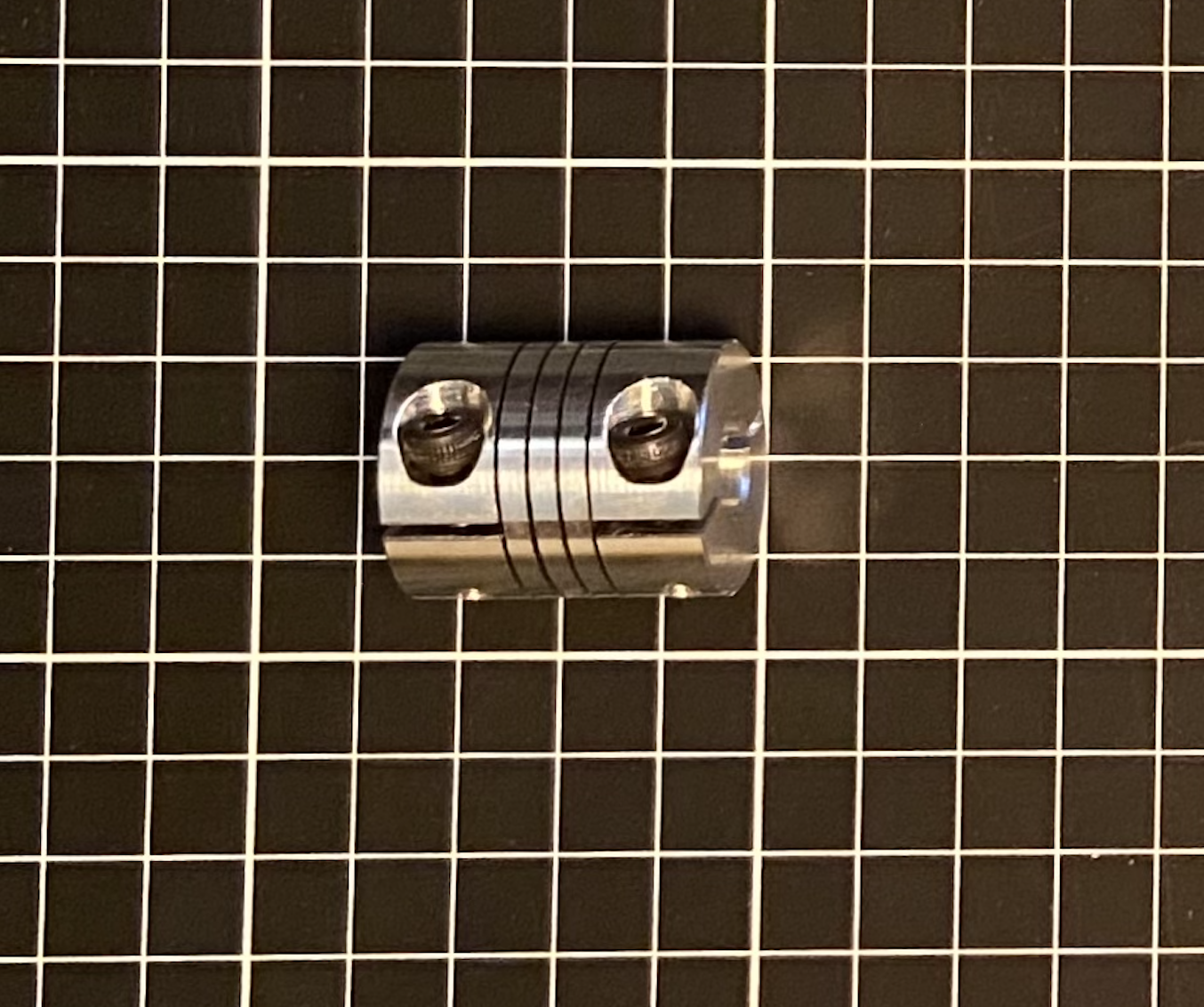
A coupler: We need to connect our motor to the crankshaft somehow. After some simple measurements, it is possible to print a custom coupler however I found that the torque tended to cause the motor side to slip. It may be possible to design a better 3D coupler, but I opted to use a metal one combined with a 3D printed one which I will explain later. (Amazon, $15 for 3)
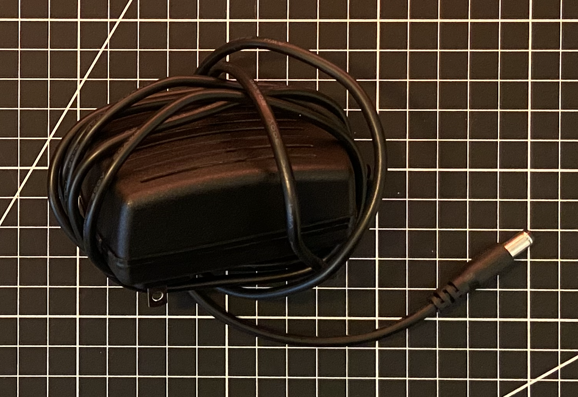
A power source: We know our motor requires a 12 V supply and our microcontroller will be powered via the motor controller which steps down the voltage for use. Since this system is close to a conveniently located outlet, a standard 12 V plug-in power supply will work well. Anything with 1-2 A should work in this case, since our motors stall current is 0.82 A and our micro controller draws 130 mA. (Amazon, $25 for 2)
All in, this cost me $56. Prices on Amazon can change frequently and I would recommend shopping around a bit before clicking buy. At least it should give you an idea of what I used. It may also be possible to get better prices elsewhere than Amazon however I am sometimes willing to pay a few extra dollars to get my parts the next day.
All the parts I used are shown below.

The Code
Let’s write some code for our automation: Assuming we have ESPHome installed, open it up and create a new configuration (the green plus button). We will need to add 2 output pins which will each control one lead on our DC motor. By selecting which pin is “on” we can control the direction, and turning them both “off” will stop the motor. We can do this by defining two switches which will control two GPIO pins.
Using a cover component, we can define our device as a window in Home Assistant and define an open, close, and stop action. There are several options for implementing covers, in this case the template cover will work best. With this we can set the open action to toggle our outputs such that the motor rotates in the forward direction, and then stops after a set amount of time. This time will depend on the speed of the motor and what the maximum position is that we desire. The close action should google our outputs so that the motor rotate in the reverse direction. The motor will continue to rotate in this direction until we tell it to stop. Although the limit switch will stop our motor when it’s closing, we should include a maximum motor run time (70s in this case) which will prevent the motor from running indefinitely if the limit switch fails. The stop action should toggle both outputs “off”. The limit switch can be defined as an input GPIO pin where it will stop the motor by calling the stop action when pressed. The action will either need to be on_press or on_release depending on if the physical limit switch is normally open or closed.
If we installed a limit switch for the fully open position, we could use the endstop cover which would allow us to approximate position based on how long the motor has been turning. In this case we can only set the motor to fully open or fully closed.
esphome:
  name: windowliving
  platform: ESP8266
  board: nodemcuv2

# Boilerplate
logger:
api:
ota:
  password: #"SHOULD AUTO GENERATE"

wifi:
  ssid: #"INSERT NAME HERE"
  password: "INSERT PASSWORD HERE"

  # Enable fallback hotspot (captive portal) in case wifi connection fails
  ap:
    ssid: #"SHOULD AUTO GENERATE"
    password: #"SHOULD AUTO GENERATE"

captive_portal:

# Define the motor control
switch:
  - platform: gpio
    id: 'motor_lead1'
    pin: D1
  - platform: gpio
    id: 'motor_lead2'
    pin: D2

# Define the cover
- platform: template
    name: "Living Room Window"
    id: living_window
    optimistic: true
    open_action:
      - switch.turn_off: motor_lead2
      - switch.turn_on: motor_lead1
      - delay: 45s
      - switch.turn_off: motor_lead1
      - switch.turn_off: motor_lead2

    close_action:
      - switch.turn_off: motor_lead1
      - switch.turn_on: motor_lead2
      - delay: 70s
      - switch.turn_off: motor_lead1
      - switch.turn_off: motor_lead2

    stop_action:
      - switch.turn_off: motor_lead1
      - switch.turn_off: motor_lead2


# Define the limit switch
binary_sensor:
  - platform: gpio
    pin: D3
    name: "Limit Switch"
    id: window_limit
    on_release:
      then:
        - cover.stop: living_window
More information on flashing this to the micro controller can be found in my other post about automating my blinds here.
Wiring
Now that the micro controller has been flashed let’s wire everything and test it to make sure it work. Ensure the correct GPIO pins are used on the micro controller as defined in the code. Everything should share a common ground. The image below shows how everything is connected.
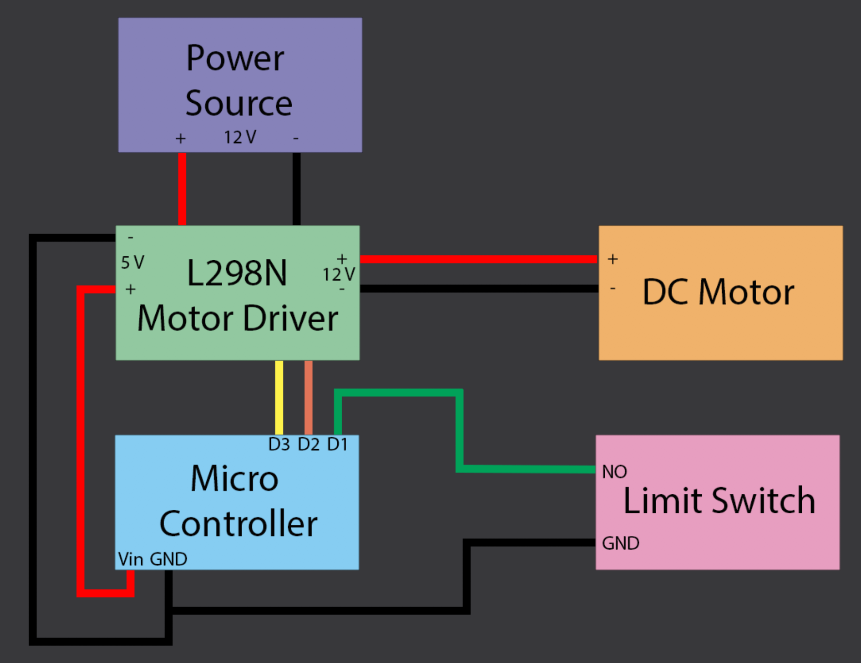
We should be able to actuate the motor now via the Home Assistant UI. The limit switch should stop the motor whenever it is pressed.
Coupling The Motor and The Crankshaft
Now, we need to figure out a method of connecting our motor to the crankshaft. The simplest method would be a direct connection as we don't need to concern ourselves with gears. Since we should have enough torque with our motor, let’s try this. Measuring the dimension of the crankshaft and the purchased motor coupling, we can create a 3D part. The unique shaped of the crankshaft requires a custom part and the purchased motor coupler will prevent our connection from slipping on the motor side. The design for the 3D part is shown below.


The printed part should connect the window shaft to the metal coupling as shown in the image to the left. The motor will connect to the other end of the metal coupling.
Another reason to keep a printed part in the coupling mechanism is that is will fail first before the motor experiences too much torque. This is a useful failsafe should something go wrong during operation and will protect our motor.
Securing The Motor
We need to secure our motor so the it can transfer torque to the crankshaft. First we need to decide on what the motor base will be attached to. Since we want the system to be removable without leaving a trace, we should use a base which will hold all our components and slide out easily. A simple 1” white board will work well as it will blend in with the window trim. This board can be seen in the image at the beginning of this post. The board needs to be the exact width of the window as it will keep the motor in place using the compressive force of the window trim. This will transfer our torque to the window shaft.
The motor can now be secured to this board. This can be done by connecting our motor to the window using the coupling and measuring the distance from the motor to the board. Measuring the screw spacing and shaft location on the motor gives us everything else we need. The design I used is shown below.

The two holes in the bottom of the motor mount will allows us to secure the mount to the board. The other four holes will secure the motor to the mount.
Securing The Limit Switch
We want to mount the limit switch to the board too as we want everything to slide off the window easily. Measuring the dimensions of the switch and the location of the mounting holes, it is possible to create a simple enclosure as shown below.

The tip of the limit switch may need to be extended depending on the distance from the windows in the closed position to the limit switch. We want the switch to be pressed exactly when the window is fully closed. This just requires a bit of measuring and another 3D printed part. With all this done, the system should look like the image below. Note that the additional part on the glass is due to the screen on my window. The limit switch cannot extend past the screen so we must added something to the window which protrudes into the screen when closed.

The Enclosure
Drawing a rectangle around the outer limits of our system gives us an idea of the smallest box we can design. Similarly we can measure the maximum height of the system to determine the minimum height of our box. A removable top means the box itself can be fastened to the board from the inside and only the lid need be removed to access our system. The image below shows the the resulting box. The one side is left open as this is facing the window and therefore out of sight. This greatly reduces the print time of what is already a lengthy print job. It would be possible to cover part of this side should that be desired however we would still need an opening for the limit switch, for the motor coupling, and for the protruding part of the installed window crank mechanism. Therefore, it is much simpler to leave this side open.

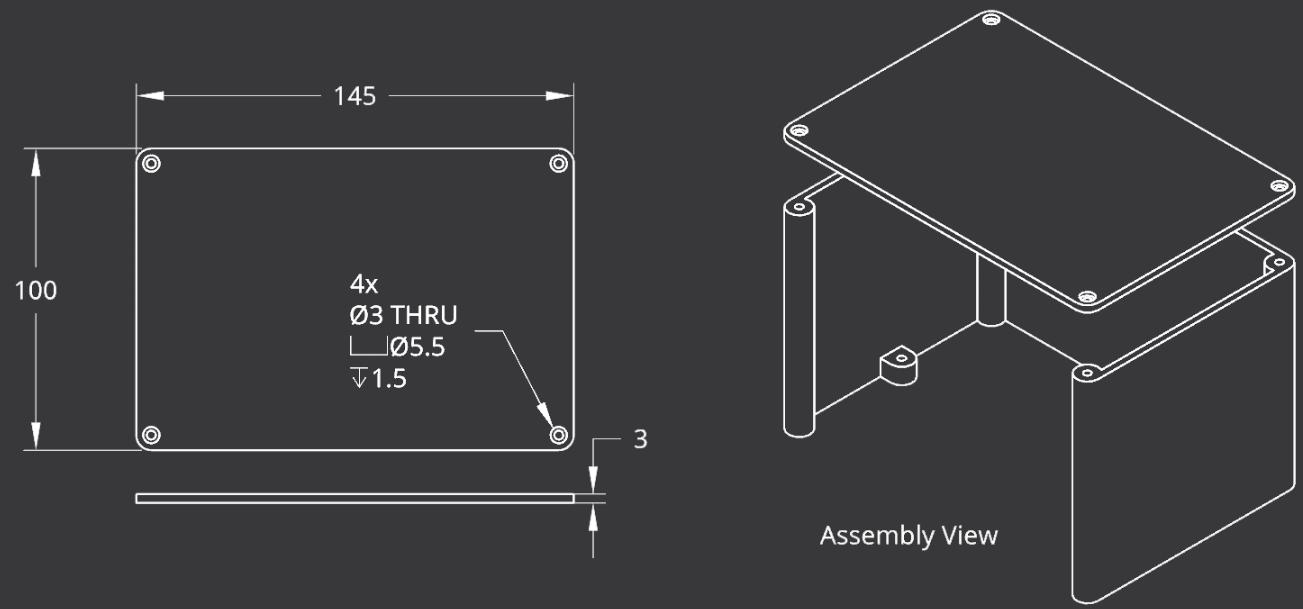
For the lid, we want it to be the same dimensions as the top of our box. Adding sunken holes will allows the screws to be flush with the top of the box. The result is shown below as well as an assembly view.
To make this system even cleaner, we can cut a small groove in the base of our board and run the power cable under our board. The final system is shown below.
Controlling The Window
I would recommend connecting a wireless button as shown in the GIF above. This ensures that there is a physical switch in the room which allows users to open and close the window. For more information on wireless buttons, check out my post about smart switches here. In this case, the automation would be something like what is shown below.

This automation let’s us toggle the window open/closed with a single press of the button and stop the window with a double press of the button as shown below.
Another useful automation to add is a notification if the window does not fully close, or if there is a problem with the limit switch. Using the close command as a trigger and giving the window time to close, we can check the status of the limit switch to determine if there was a problem. The automation can then send a notification to our phone, as shown below.

The following code implements this.
alias: Notify Window Error
description: ''
trigger:
  - platform: state
    entity_id: cover.living_room_window
    to: closed
condition: []
action:
  - delay:
      hours: 0
      minutes: 1
      seconds: 10
      milliseconds: 0
  - condition: state
    entity_id: binary_sensor.living_window_state
    state: 'on'
  - service: notify.mobile_app_phils_iphone_11
    data:
      title: Living Room Window Alert
      message: There may be a problem closing the living room window!
mode: single
P.S. I was featured in Home Assistants first ever newsletter! Check it out for some other cool ideas and inspiration!