How I Automated My Blinds to Tilt With The Push of a Button

Let me give you some hypotheticals. What if your blinds could open at the exact moment you woke up? What if your blinds could close whenever the sun was starting to heat your house too much during the summer? Or more simple still, what if you could press a button and all your blinds closed to get ready for bed, or maybe to set your living room into “movie mode”. These are but a few potential automations the are possible by creating controllable blinds. If any of that sounds interesting to you, then read on!
Constraints and Part Selection
The system needs to be able to tilt the blinds between fully closed and fully open. It also needs to be easily removable so that the regular tilt mechanism can be reinstalled if ever we need to - I won’t live in my condo forever! The system should be concealed as much as possible. We also want to control our system in an intuitive manner which makes it easier than before.
Let’s consider the components of the system:
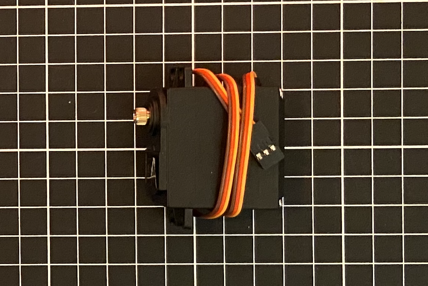
A motor: We need some kind of motor to turn the blinds between open and closed states. In this case, it is important to be able to control intermediate positions (i.e. partially open/closed). The torque we need is nothing crazy either. This seems to indicate servo motors would be suitable. A stall torque around 12 kg-cm should be sufficient in this case and we want to make sure it is able to rotate 180 degrees. We want it to fit inside out existing blinds so something small is ideal as well. The ones I link to below worked well for me. (Amazon, $36 for 4)
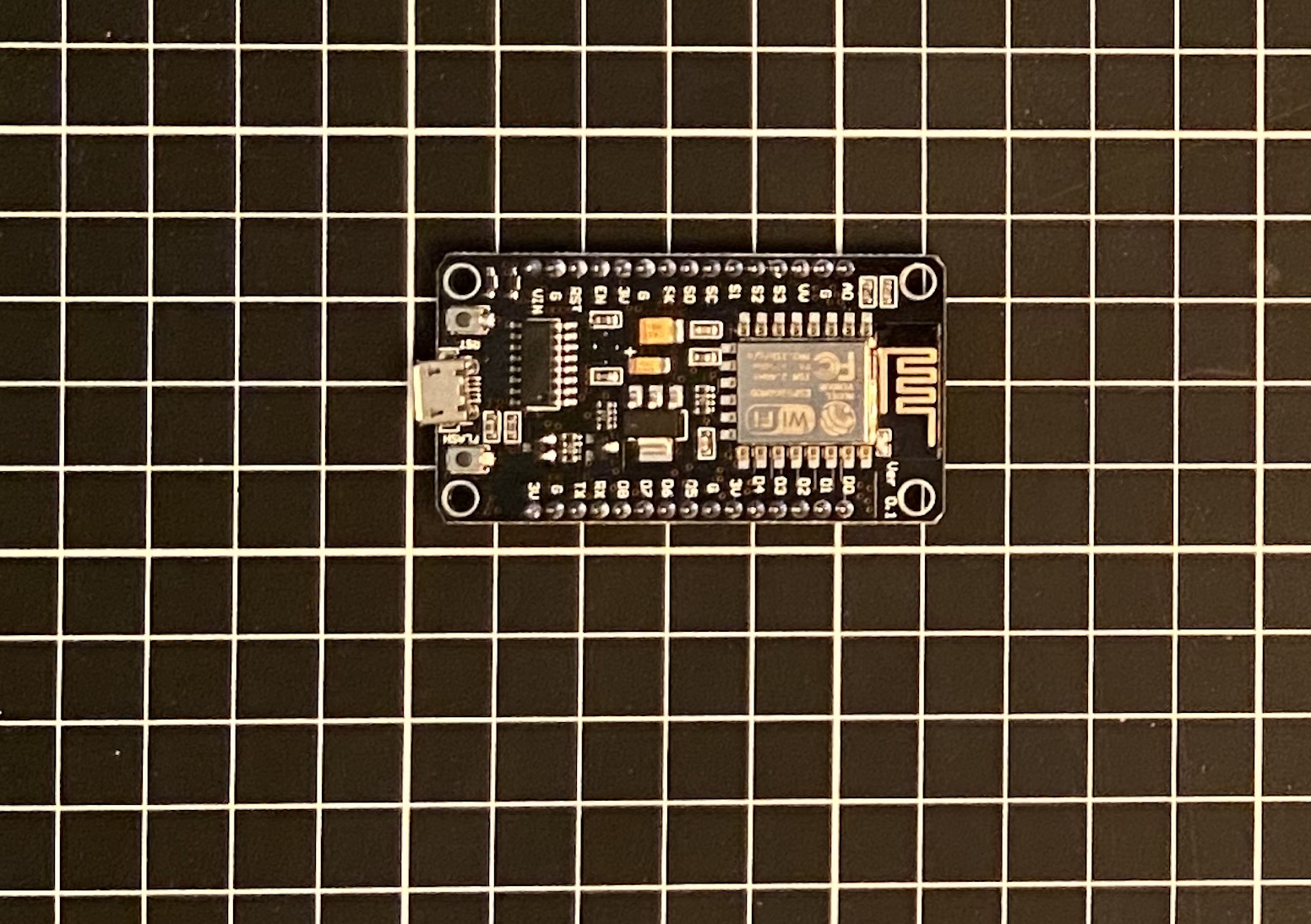
A micro controller: The simplest way to interface a microcontroller with Home Assistant is to use something which works with ESP Home (if you don’t know about ESP Home prepare to be amazed! Read about it here). This requires a device with an ESP32 or ESP8266 chip. We don’t need many inputs or outputs, just a few GPIO pins. The Node MCU ESP8266 should work since they are relatively cheap, easy to source and work well with Home Assistant using ESP Home. Amazon sells them for less than $10 a piece and you can get them within a few days. (Amazon, $19 for 3)
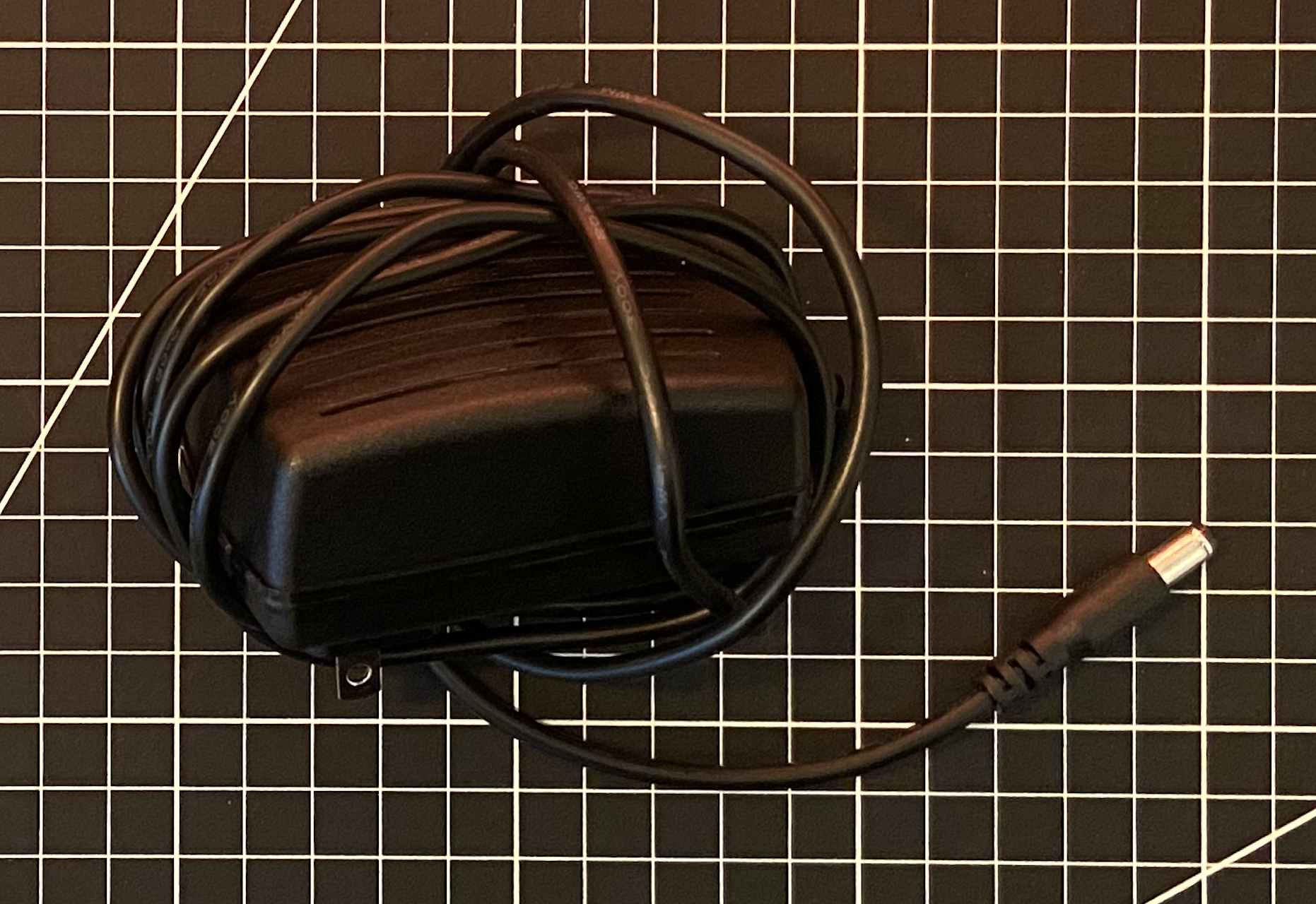
A power source: We know the input voltage of our motor is 4 V to 7 V. Our microprocessor can accept voltages in this range so it does not change our range. A 6 V supply with with 1 A should work in this case, since our motor draw 100 mA and our micro controller draws 130 mA. (Amazon, $25 for 2)
All in, this cost me $28. Prices on Amazon can change frequently and I would recommend shopping around a bit before clicking buy. At least it should give you an idea of what I used. It may also be possible to get better prices elsewhere than Amazon however I am sometimes willing to pay a few extra dollars to get my parts the next day.
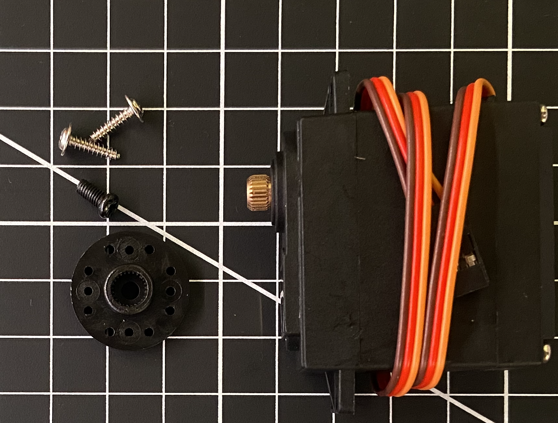
All the parts I used are shown below.
The Code
Let’s write some code for our automation: Assuming we have ESPHome installed, open it up and create a new configuration (the green plus button). We can assign an output pin to a PWM signal and use the servo component to control this output. The code will look something like what is below. For more information on using the servo component, the ESPHome website does a good job explaining it here.
esphome:
  name: masterblind1
  platform: ESP8266
  board: nodemcuv2

# Enable logging
logger:

# Enable Home Assistant API
api:
  services:
    - service: control_servo
      variables:
        level: float
      then:
        - servo.write:
            id: servo_master1
            level: !lambda 'return level / 100.0;'

ota:
  password: #"SHOULD AUTO GENERATE"

wifi:
  ssid: "INSERT NAME HERE"
  password: "INSERT PASSWORD HERE"


  ap:
    ssid: #"SHOULD AUTO GENERATE"
    password: #"SHOULD AUTO GENERATE"

captive_portal:

output:
  - platform: esp8266_pwm
    id: 'tilt'
    pin: D1
    frequency: 50 Hz

servo:
  - output: 'tilt'
    id: servo_master1

There are a few methods to initially flash this to our micro controller. I prefer plugging it directly into my Raspberry Pi which is running Home Assistant. Then all we need to do is click “Install” and then select our device. Let the device do it’s thing and it should reboot on its own when finished. At this point it should connect to our wifi network. The device should now be discoverable in Home Assistant using the ESPHome integration. More information on flashing can be found here.
This is not the end of our work with Home Assistant as it does not currently natively support servos. We need to add some code to two separate places. First, we need a slider which will control our blinds within Home Assistant. Second, we need an automation which will change the position of our blinds when the slider value is changed. The trigger will be a change in our input slider and the action will be moving the blinds to the that new slider value. In the configuration file, the code will look something like this.
input_number:
  master_blind1_tilt:
    name: Master Blind1 tilt
    initial: 0
    min: -100
    max: 100
    step: 1
    mode: slider

automation:
  alias: kitchen blinds tilt 1
  description: ''
  trigger:
  - platform: state
    entity_id: input_number.kitchen_blinds_tilt1
  condition: []
  action:
  - service: esphome.kitchenblinds_control_servo1
    data_template:
      level: '{{trigger.to_state.state | int }}'
  mode: single
Note: Remember to restart Home Assistant as this is required to start using what we added!
Connecting To The Tilt Shaft
Now, we need to figure our out to connect our motor to the tilt shaft inside the blinds. There is no room on either end of the shaft to directly connect the motor. Using gears, we can mount the motor in series with the shaft. One will be fixed to the motor and one fixed on the shaft of the blinds. By measuring the shape and dimensions of the rod we can determine the interior hollow shape of our Gear #1. Let's go with a 1:1 gear ratio to simplify things since we won’t need to take advance of gear ratios. Placing the motor inside our blinds and measuring the distance from the motor to the shaft will give us the outer dimension of our gears. Selecting a number of teeth such as 10 seems appropriate in this case.
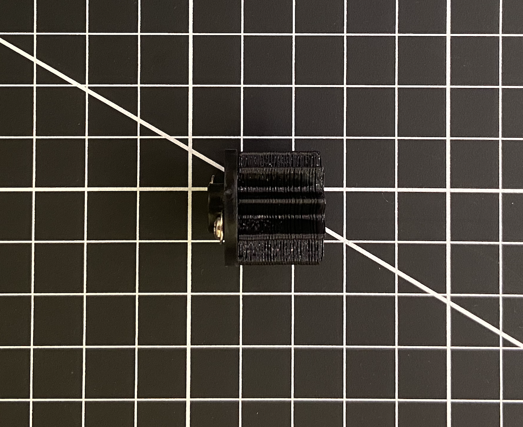
Gear #2 must be fastened to the motor. In this case the motor comes with a circular fastening piece and some screws. By adding two small holes to Gear #2 we can take advantage of this. Both of these gears can be seen below.
Note: All dimension are in mm. Since the size and shape of the teeth are identical for both gears, they are only dimensioned on Gear #2.
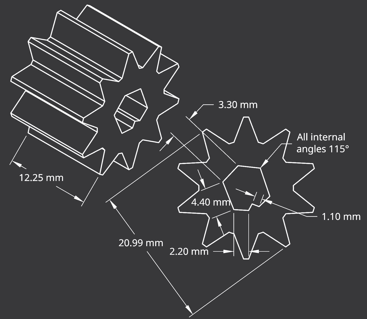
Gear #1

Gear #2
Wiring
Let’s wire our system and test it. The image below shows how we want to connect our system. Ensure the GPIO pin on the mircrocontroller connected to the motors PWM input is the one defined in your code. Also, check that the motor and the microcontroller share a common ground. We can now try connecting to the micro controller wirelessly and test that the motor turns using the slider within Home Assistant.

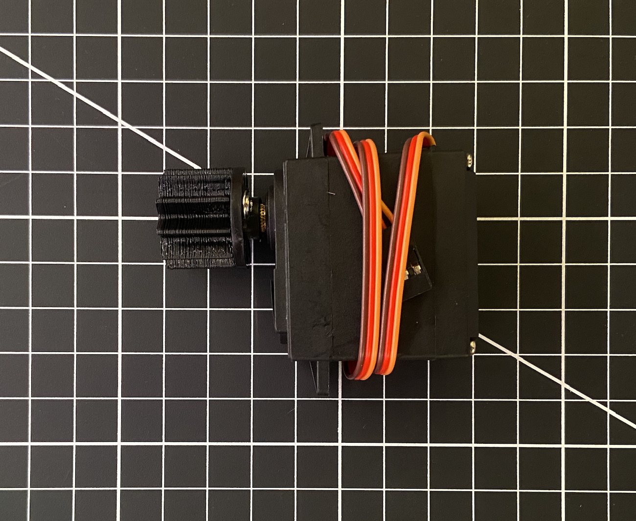
Connecting The Gear and The Motor
Let’s assemble the motor and Gear #2: We will need the circular fastening plate that came with the motor, as well as two of the small silver screws and the single black screw. Use the two silver screws to fasten Gear #2 to the circular plate. Ensure the screw heads will be facing the motor. Mount the circular plate to the motor using the black screw. Do this by dropping it through the centre of Gear #2. This process is shown below.
The Final Assembly
Now let’s mount the motor assembly inside of our blinds: Remove the endcap from the blind enclosure and remove the current manual tilting mechanism. Slide the shaft out to install the micro controller and the motor with Gear #2. Slide Gear #1 onto the shaft and it is move back into position. A spacer needs to be placed in the small gap between the wall and the motor to prevent the motor from moving out of position. In this case I had some spare rigid foam. The image below shows the final result with all that’s left being to connect the positive and negative terminals of the power supply.

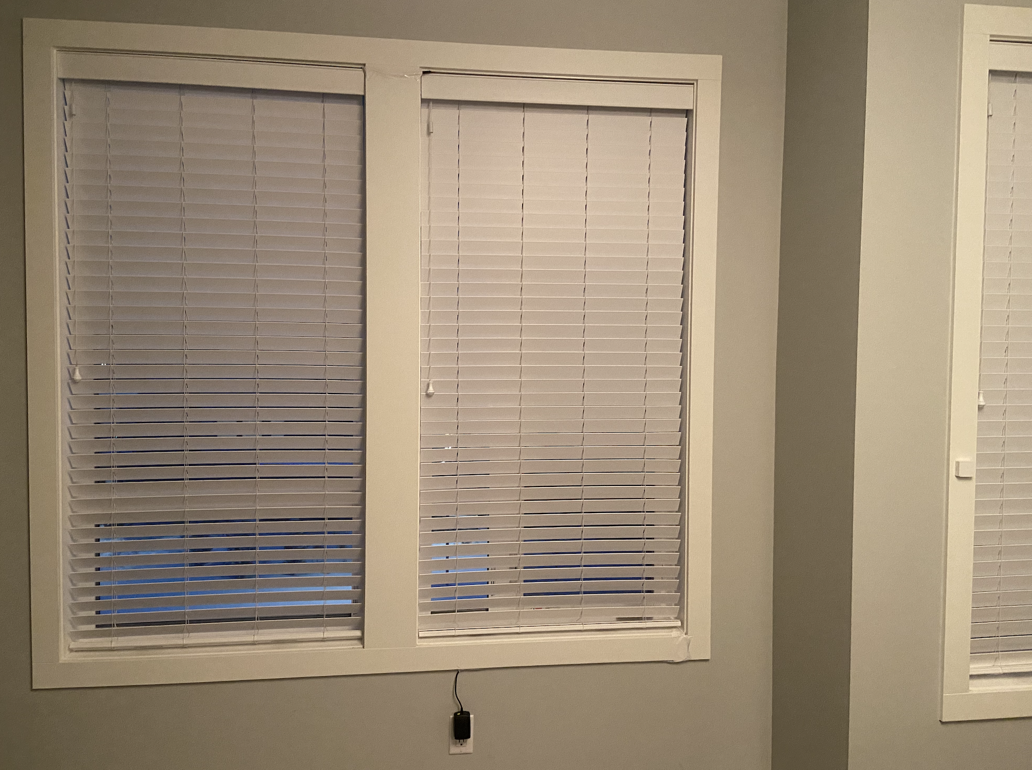
Once installed, we can run some wiring for the power supply down the edge of the window and cover it with some white packing tape. After connect the power source to an outlet, the blinds should be operational and controllable using Home Assistant.
Controlling The Blinds
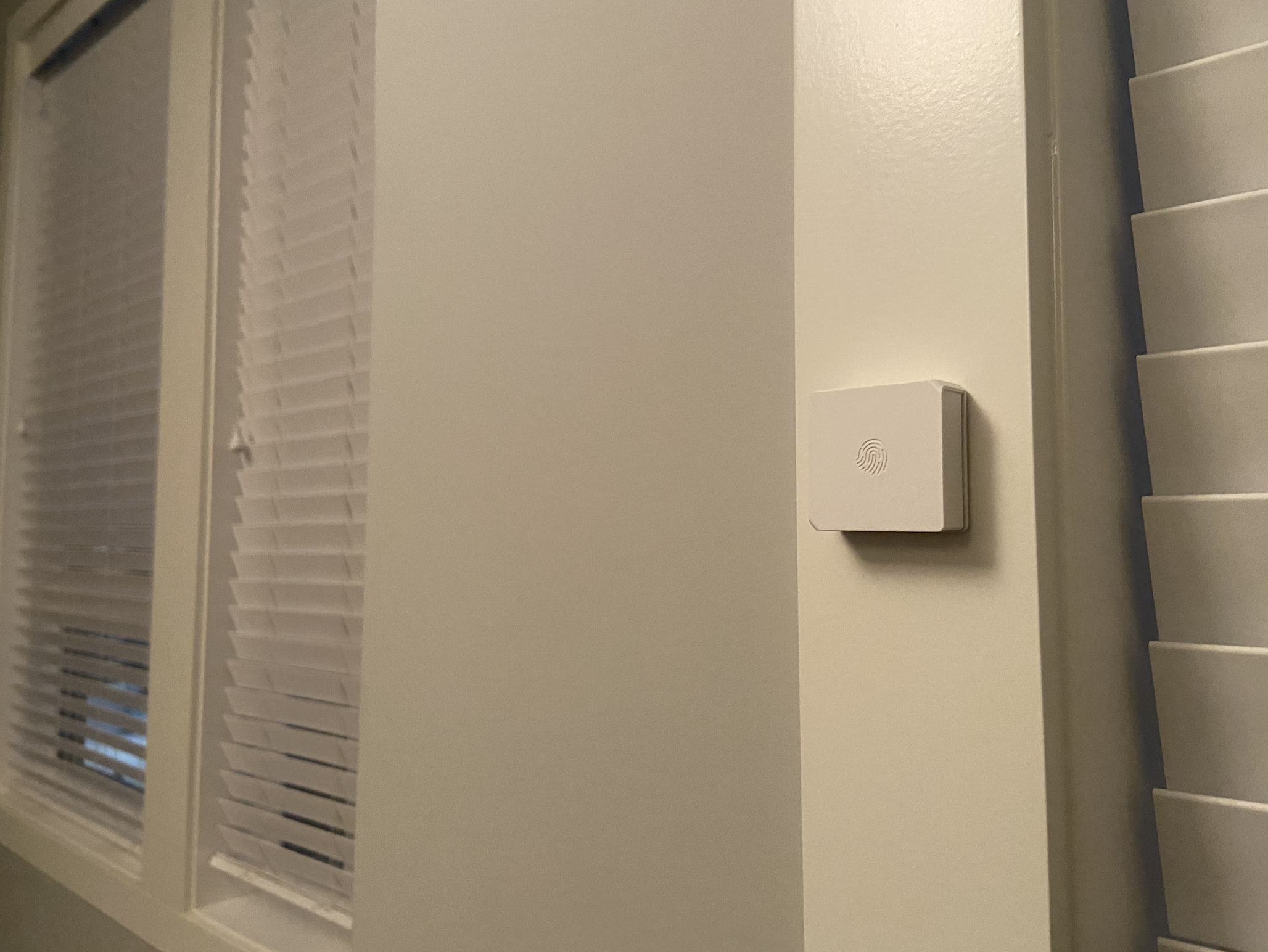
I like having a physical button within the environment. It makes the system easier to use and when others are over, they are able to control the system as well. To read a bit more on setting up a wireless button within Home Assistant, check out my post on smart lights here. The button I like has three triggers, single press, double press, and long press. In this case I will use the single press to open and close my blinds. This will look like the image below when implementing the automation in Home Assistant. Note that -30 is fully closed and 100 is fully open. I only tilt my blinds in one direction so this works well for me. If the other direction of tilt is desired, it is possible to install the motor with a different initial position. Note that other blinds could be controlled from the same switch using the other triggers if desired.

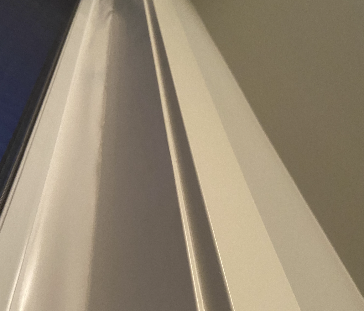
The images below show the fully open and closed states, as well as the button placement on the right side. By using white packing tape to conceal the wiring, it is very difficult to see the wires connecting the blinds to the power source. The final image shows how I conceal the wires running up to the top of the blinds.
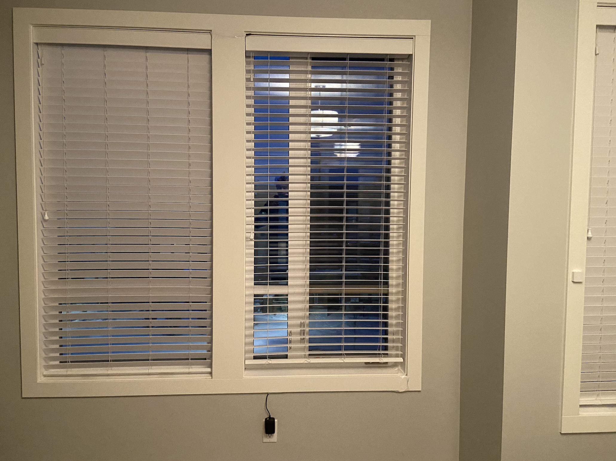
You might be able to notice the wires connecting the pair of blinds at the top. In this case, it is possible to control multiple blinds using the same micro controller. This results in the second set of blinds only costing $9(the cost of the motor)! I simply connected the new blinds to a different output pin on the same micro controller and made this a PWM output much like the first one. Since would need to run power to the new blinds anyways, it makes sense to run 1 extra wire with the PWM signal, rather than using another micro controller.
Comments and Future Considerations
Reflecting on this project, there are certainly improvements which we could consider. For example, investigating a form of battery power would certainly save us some wiring. However, these little controllers consume a surprisingly high amount of power, mostly because of their constant communication over wifi. This system only deals with tilting the blinds, which is how I interact with the blinds 90% of the time. Adding a mechanism to raise and lower the blinds would be an interesting addition.